TL866
NOTE: these pages were imported from minipro wiki
This wiki is dedicated to gathering information about the AutoElectric MiniPro TL866 programmer.
The TL866 is a universal EEPROM, FLASH, 8051, AVR, MCU, GAL, PIC, SPI chip programmer supporting around 13,000 chips.
Pages
- Tl866 supported chips
- Tl866 sellers
- Hardware
- Software
- Autoelectric Minipro : vendor provided Windows client
- Vdudouyt Minipro : FOSS Linux client
- Radioman TL866 updater : firmware updater tool
- opentl866 : FOSS firmware
Difference between TL866A and TL866CS
There're two version of the TL866 programmer, the TL866A with ICSP header and TL866CS without ICSP.
TL866A has the ICSP header and TL866CS does not, otherwise the devices are physically the same. The TL866CS is also factory programmed to not use the ICSP header.
This means that TL866A supports (in addition to all the chips TL866CS supports):
- Microchip ICSP support for some chips (in circuit programming)
- ICSP support for ATmega and SYNCMOS MCU SM89xxx SM59xxx (in circuit programming)
- AT45DBxxxx ICSP, programmable only on TL866A
TL866 II PLUS is NOT compatible
Although the TL866 II PLUS is in an identical plastic enclosure, it is NOT compatible with the TL866A and TL866CS. The TL866 II PLUS is based on different PCB with PIC24FJ256 microcontroller.
Counterfeit programmers
There have been reports of a counterfeit version of the tl866 out of aliexpress. If you end up with one of these the official software will detect it and erase the contents of the PIC onboard. It is theorized that the detection is due to sloppy piracy resulting in the serial number of all the fakes being the same. To restore your device you now need to go though the operation to upgrade it to a tl866a.
Autoelectric has provided this image to help identify counterfeit programmers without first bricking them with the official Minipro software.
ICSP
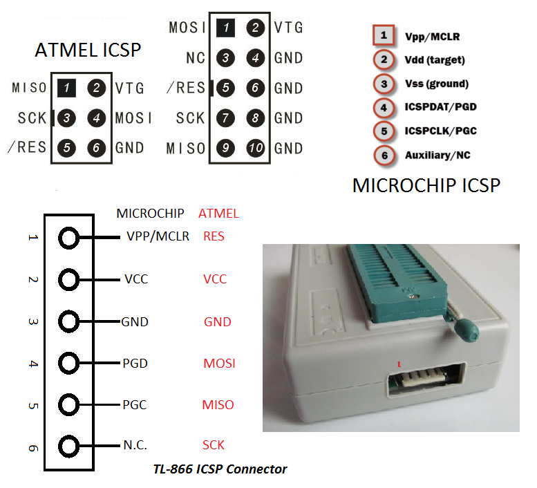
ICSP connections are usually deductible from the MiniPro software.
You select the chip, click the ICSP programming option (if available) and then the Information button. This will display a image with the appropriate connections.
The images are also available in the img directory in your MiniPro directory
Handy helper image
Source. Thanks radioman!
Schematic
The schematic in PDF format is available in TL866_schematic.pdf by Radioman.
It's intended use is a better understanding of the TL866 internal workings and is available here purely for experimental and educational purposes.
Photos
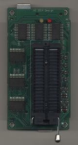
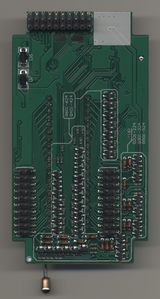
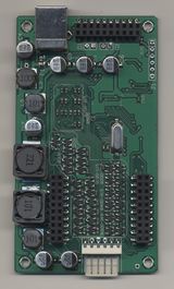
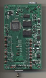
TL866 A photos
Photos of a TL866 A bought April 2018 from eBay seller xgautoelectric.
Red and yellow LEDs were desoldered from mainboard to allow separation of the two PCBs.
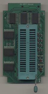
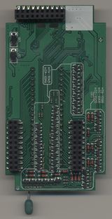
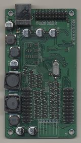
TL866 CS photos
Photos of a TL866 CS bought April 2018 from eBay seller xgautoelectric.
Red and yellow LEDs were desoldered from mainboard to allow separation of the two PCBs.
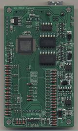
External VDD control
Experiment to read bit rotted MCUs by under voltaging
Do:
- Remove Q11 (overcurrent control transistor)
- Solder external voltage to net VDD (Q11 middle lead)
- Remove R39 (disable spurious overcurrents by removing Q11)
- Note: should be able to do this for VPP if desired as well (Q9)
Reference experiment: a good Intel 27128 was able to read its ROM down to 3.22V before bits started to convert to 1
