BPM Programmer: Difference between revisions
No edit summary |
m (fix nomenclature) |
||
| (24 intermediate revisions by 3 users not shown) | |||
| Line 3: | Line 3: | ||
[[Category:Hardware]] | [[Category:Hardware]] | ||
=BP series= | =BP series= | ||
| Line 177: | Line 176: | ||
|1600 | |1600 | ||
| | | | ||
|CPCB12A Rev. C | |CPCB12A Rev. C 2001 | ||
|Intel | |Intel FC80486DX4100 | ||
| | |72-pin SIMM | ||
Unpopulated | |||
|(handwritten) | |(handwritten) | ||
MUS | MUS | ||
28781 | 28781 | ||
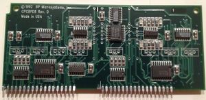
| | |CPCBPD8B Rev A 1999 | ||
| | |CPCBVLVTA REV. B 2000 | ||
|29203118-C2 | |29203118-C2 | ||
REV-C C2 | REV-C C2 | ||
| Line 525: | Line 525: | ||
[[File:pd_bpm_bp-1400_mb2.jpg|frameless]] | [[File:pd_bpm_bp-1400_mb2.jpg|frameless]] | ||
Technology adapter: | |||
[[File:pd_bpm_bp-1400_mez_top.jpg|frameless]] | [[File:pd_bpm_bp-1400_mez_top.jpg|frameless]] | ||
| Line 744: | Line 744: | ||
==Parallel to USB upgrade== | ==Parallel to USB upgrade== | ||
Main page: [[ | Main page: [[BPM_WWAVUSBEPP]] | ||
==USB hub== | ==USB hub== | ||
| Line 772: | Line 771: | ||
==EP-1140== | ==EP-1140== | ||
[[File:BP_EP_1140_Top.jpg|frameless|480px]]<br \><br \> | |||
PC interface: parallel port | '''PC interface:''' parallel port<br \> | ||
'''Chip interface:''' DIP-40<br \> | |||
'''CPU:''' Intel 8088<br \> | |||
'''Memory:''' 8KB/32KB SRAM<br \> | |||
'''Firmware:''' 8KB/16KB/32KB EPROM<br \><br \> | |||
[[File:BP_EP_1140_PCB_Front.jpg|frameless|480px]]<br \><br \> | |||
[[File:BP_EP_1140_Parallel.jpg|frameless|160px]] | |||
[[File:BP_EP_1140_CPU.jpg|frameless|160px]] | |||
[[File:BP_EP_1140_Linear_Supply.jpg|frameless|160px]]<br \> | |||
[[File:BP_EP_1140_Variable_Supply.jpg|frameless|240px]] | |||
[[File:BP_EP_1140_IO_Ground.jpg|frameless|240px]]<br \><br \> | |||
'''Jumpers:'''<br /> | |||
*EPROM Type | |||
**Left = ON for 27256, OFF for 2764/27128 | |||
**Middle = ON for 27128/27256, OFF for 2764 | |||
*SRAM Type | |||
**Right = ON for 62256*, OFF for 6264 | |||
''ON = Up/Towards xtal''<br /> | |||
''OFF = Down/Away from xtal''<br /> | |||
(* Note: Even if the firmware can deal with more RAM, BPDos/BPWin might expect it to be hardcoded and crash the programmer if not set right.)<br /> | |||
Powersupply: | '''Powersupply:''' | ||
*Unregulated | *Unregulated | ||
**-13.4V/+11.1V | **-13.4V/+11.1V | ||
| Line 784: | Line 803: | ||
**+5V (TTL, CPU, DAC) | **+5V (TTL, CPU, DAC) | ||
**+6V (CMOS) | **+6V (CMOS) | ||
**+ | **-3V/+29V (Op-Amps) | ||
*Variable | |||
**Overcurrent-protection | |||
**13 DACs (DAC0830LCN) | |||
**4 quad op-amps (TL084CN) | |||
*Routing | |||
**12 transistors for VCC/VPP (NSDU01) | |||
**11 transistors which has something to do with VPP-pins (PN2222) | |||
**8 transistors for GND (IRF-Z15) | |||
'''Pinout:''' | |||
*20 normal IO pins | |||
*1 pin with VCC feature | |||
*11 pins with VPP feature | |||
*8 pins with GND feature | |||
*Out of all the pins, 4 have some unknown additional feature | |||
<nowiki>Pin features: | |||
* | ______ _____ _____ ______ | ||
** | _ VPP |_| VCC _ | ||
* | _ Pin* Pin _ | ||
_ Pin* VPP _ | |||
* | _ GND VPP _ | ||
___ Pin VPP ___ | |||
_ Pin VPP _ | |||
_ VPP VPP _ | |||
_ Pin Pin _ | |||
_ Pin VPP _ | |||
______ Pin VPP ______ | |||
_ GND GND _ | |||
_ GND Pin _ | |||
_ Pin Pin _ | |||
_ GND Pin _ | |||
___ Pin VPP ___ | |||
_ GND VPP _ | |||
_ Pin Pin _ | |||
_ GND* Pin _ | |||
_ Pin* Pin _ | |||
______ GND_____________Pin ______ | |||
* Unknown additional feature | |||
</nowiki> | |||
=PLD series= | =PLD series= | ||
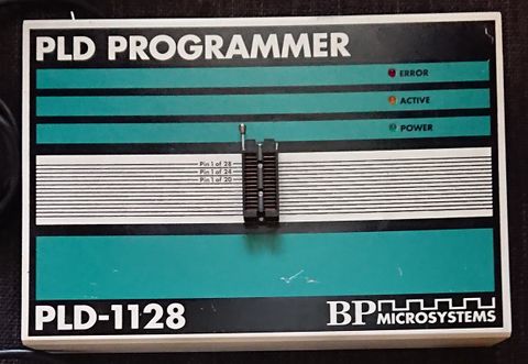
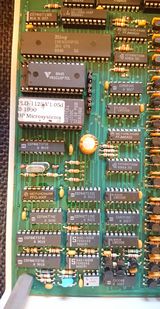
==PLD-1128== | ==PLD-1128== | ||
[[File:BP_PLD_1128_Top.jpg|frameless|480px]]<br \><br \> | |||
PC interface: parallel port | '''PC interface:''' parallel port<br \> | ||
'''Chip interface:''' DIP-28<br \> | |||
'''CPU:''' Zilog Z80<br \> | |||
'''Memory:''' 2KB/8KB SRAM<br \> | |||
'''Firmware:''' 8KB/16KB/32KB EPROM<br \> | |||
[[File:BP_PLD_1128_PCB_Front.jpg|frameless|480px]]<br \><br \> | |||
[[File:BP_PLD_1128_Parallel.jpg|frameless|160px]] | |||
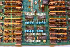
[[File:BP_PLD_1128_IO_Upper.jpg|frameless|240px]] | |||
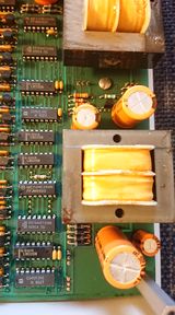
[[File:BP_PLD_1128_Linear_Supply_Upper.jpg|frameless|160px]]<br \> | |||
[[File:BP_PLD_1128_CPU.jpg|frameless|160px]] | |||
[[File:BP_PLD_1128_IO_Lower.jpg|frameless|240px]] | |||
[[File:BP_PLD_1128_Linear_Supply_Lower.jpg|frameless|160px]]<br \><br \> | |||
'''Jumpers:'''<br /> | |||
*EPROM Type | |||
**W1 = ON for 2764/27128, OFF for 27256 | |||
**W2 = ON for 2764 , OFF for 27128/27256 | |||
*SRAM Type | |||
**W3 = ON for 6116, OFF for 6264* | |||
*Unknown | |||
**Jumper up by the parallel port = ?? | |||
''ON = Up/Towards CPU''<br /> | |||
''OFF = Down/Away from CPU''<br /> | |||
(* Note: V1.05d firmware only supports 6116-type SRAM) | |||
Powersupply: | '''Powersupply:''' | ||
*Unregulated | *Unregulated | ||
**-10.9V/+10.3V | **-10.9V/+10.3V | ||
| Line 812: | Line 886: | ||
**-5.8V/+30V (Op-Amp) | **-5.8V/+30V (Op-Amp) | ||
**Possibly more | **Possibly more | ||
=CP series= | =CP series= | ||
Latest revision as of 15:06, 30 January 2024
BP series
| Vendor | Model | Year | Motherboard
silkscreen |
Motherboard
CPU |
Motherboard
RAM |
Motherboard
FPGA sticker |
Card
Model |
Tech adapter
silkscreen |
Power supply | Accessory | Last BPWin | Note |
|---|---|---|---|---|---|---|---|---|---|---|---|---|
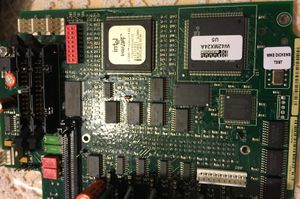
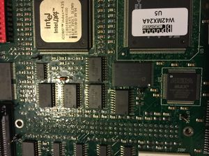
| Actel | SS2 | 2001 | CPCB12A Rev. C | Intel FC80486DX4100 | Populated | U5
W42MX24A BP MICROSYSTEMS 09/20/02 |
CPCBPD8B Rev B
2001 |
CPCBVLTA REV. B
2000 |
Button | mcmaster | ||
| Actel | SS3 | 2008-05-12 |
WWAV12F
REV.F M0309
|
Intel UG80486DX4100 | SO DDR
Populated
512 MB |
CPCBPD8B Rev B
2001 |
SWG
CEM-??
REV-A1 |
|||||
| BPM | 1148 | |||||||||||
| BPM | 1200 | 1992 | BP-1200 Rev C | AMD N80L286-16/S | N/A | CPCBPD8 Rev. D | INTEGRATED POWER DESIGN |
|||||
| BPM | 1400/84 | |||||||||||
| BPM | 1400
(1400/240) |
CPCB11 Rev. G | 80C286 | CPCBTA240V REV. D | 29203118-C2
REV-C C2 |
|||||||
| BPM | 1410/84 | 2005 | CPCBD03223 Rev. F
2005 |
Intel 80486DX4100 | SO DDR
Unpopulated |
N/A | CPCBPD8B Rev B
2001 |
2002 BP MICROSYSTEMS | Model?
Looks like SS3 CEL-22-000000001560 E145540, CS155-F3 HP-OK, REV A |
mcmaster | ||
| BPM | 1410
(1410/240) |
|||||||||||
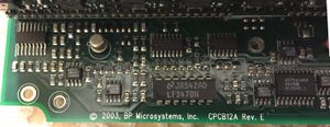
| BPM | 1600 | CPCB12A Rev. C 2001 | Intel FC80486DX4100 | 72-pin SIMM
Unpopulated |
(handwritten)
MUS 28781 |
CPCBPD8B Rev A 1999 | CPCBVLVTA REV. B 2000 | 29203118-C2
REV-C C2 |
5.33.0 | |||
| BPM | 1610 | |||||||||||
| BPM | 1700 | |||||||||||
| BPM | 1710 | |||||||||||
| BPM | 2000 | |||||||||||
| BPM | 2100 | |||||||||||
| BPM | 2200x4/240 | 1998 | CPCB11 Rev. F
1998 |
Harris CS80C286-16 | CPCBPD8A Rev D
1997 |
Top
CPCBTA240V REV. D 1996
CPCBTA240V Rev. D 1996 |
29203118-C2
REV-C C2 |
4.73.0 | mcmaster
REV vs Rev is inconsistent even on the same PCB... | |||
| BPM | 2500 | |||||||||||
| BPM | 2510 | |||||||||||
| BPM | 2600 | |||||||||||
| BPM | 2600M | |||||||||||
| BPM | 2610 | |||||||||||
| BPM | 2700 | |||||||||||
| BPM | 2700M | |||||||||||
| BPM | 2710 | |||||||||||
| BPM | 2800F |
General notes:
- The following are the same basic hardware
- BP-1400, BP-2200
- BP-1410, SS3
- BP-1600, SS2
- Power supplies
- Three generations
 (11:36:56 PM) Lord_Nightmare: the main processor [of the bp1200] is an 80286-16, with a 32mhz xtal
 (11:37:07 PM) Lord_Nightmare: [the board labeled] std48, it would [I assume] normally have [std48] printed on it nicely
 (11:37:22 PM) Lord_Nightmare: this one was a refurbished unit and i guess they used an unprinted metal case for that pcb
 (11:37:37 PM) Lord_Nightmare: std48 is the 'relay pcb'
 (11:37:38 PM) digshadow: but whats the point
 (11:37:52 PM) Lord_Nightmare: i think it controls which pins are powered with what [rail] but am not sure
 (11:38:06 PM) digshadow: gotcha
 (11:38:07 PM) Lord_Nightmare: the bp1200 it is a 'separate' pcb on top of the unit
 (11:38:13 PM) digshadow: but its basically part of the unit right
 (11:40:54 PM) Lord_Nightmare: the bp1600 has the 'relay board' integrated as a board which sits on top of the rest of the inside of the unit inside the case
 (11:41:16 PM) Lord_Nightmare: i think the 1400 does as well
 (11:41:33 PM) Lord_Nightmare: while on the 1200 it sat on top of the unit
 (11:46:35 PM) Lord_Nightmare: the most basic bp unit was the bp-1148 "device programmer"
 (11:46:55 PM) Lord_Nightmare: note the case is identical to the 1200, and the only difference [in appearance] is 'universal' is blacked out on the wording
 (11:47:11 PM) Lord_Nightmare: http://vertassets.blob.core.windows.net/image/107fdcf5/107fdcf5-2dad-11d4-8c3d-009027de0829/bp1148.jpg
 (11:47:46 PM) Lord_Nightmare: that picture is a mockup, the std48 'layer' is missing
 (11:48:11 PM) Lord_Nightmare: http://thumbs.ebaystatic.com/d/l225/m/m1qMyAgqacqzlOo4KbeZLcw.jpg shows an actual 1148
ECO: WWAV20-4
- http://www3.bpmmicro.com/web/helpandsupport.nsf/69f301ee4e15195486256fcf0062c2eb/66634b97cb53c22e8625703e0062b99a!OpenDocument
- Effect 1: ECO: WWAV20-4 Effect 2: CPCB11 Rev A-F - TA-84 will occasionally fail relay test
http://www3.bpmmicro.com/web/helpandsupport.nsf/WebKeys/BPM-7Q2R96!OpenDocument
| BP-1148, BP-1200, BP-2000, BP-2100, BP-2500, BP-2510, BP-2600M Final Software Version |
| Legacy Programmer Last Software Version Reference |
| Per the following document, the final BPWin version for the legacy programmers listed above is BPWin 4.73.
http://www3.bpmicro.com/Web/helpandsupport.nsf/WebKeys/BPM-6AHS6M?opendocument&Cat=FAQ You can download BPWin 4.73 from our software download page by clicking the "BPM Legacy Software Download" link in the upper-left corner of the page.
|
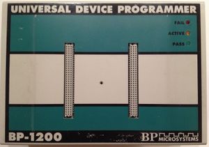
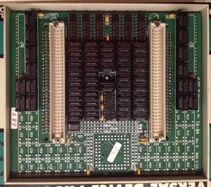
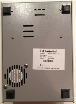
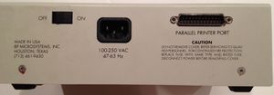
BP-1200
PC interface: parallel port
Chip interface: 2 plug SM
http://atariage.com/forums/topic/142884-bp-microsystems-eprom-programmer-a-cry-for-help/
- IF you get a TA-84 pin driver module (and a SM48D 48-pin DIP module, but NOT the one that comes with the BP-1148) it will convert your BP-1148 to a BP1200/84.
BP-1400
PC interface: parallel port
Chip interface: 3 plug SM
BP-1400/84: [1]
BP-1400/240: [2]
EOL notice
http://www3.bpmmicro.com/web/helpandsupport.nsf/WebKeys/BPM-7AUPV7!OpenDocument&Cat=Issue&Click=
End of Life for 1400 and 2200 model programmers
Summary BPM announces the planned end of support for the 1400 and 2200 model programmers on December 31, 2008. Introduced in 1996 and discontinued in 2005, the 2200 and 1400 were the first in the industry to enable fine control of programming waveforms for the highest quality programming with the widest device support capabilities. Limitations of the original programmers hardware combined with new software compatibility and component obsolescence forces this end of support announcement.
Details End of support means that BPWin software released in 2009 will not support the 1400 and 2200 model numbers. These models can continue to function with existing BPWin software released prior to 2009, but will not be eligible for additional algorithms or updates to existing algorithms. Hardware contracts will also not be available for these programmers. Also, repairs and calibration of these programmers are no longer possible.
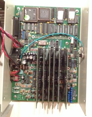
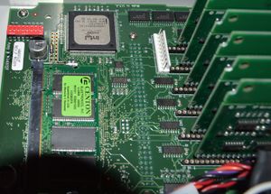
Motherboard
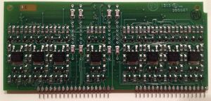
Technology adapter:
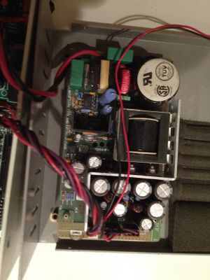
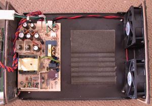
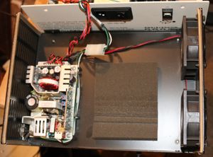
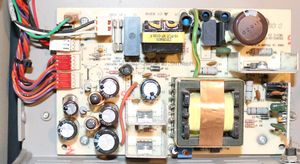
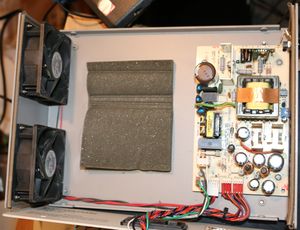
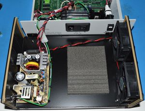
Power supply
BP-1410
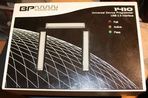
External:
Power supply:
PC interface: USB
Chip interface: 3 plug SM
BP-1410/84 datasheet: [3]
BP-1410/240 datasheet: [4]
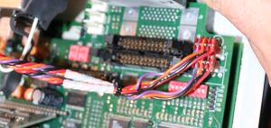
Motherboard
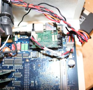
Motherboard USB connector:
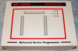
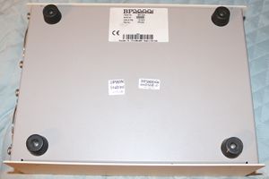
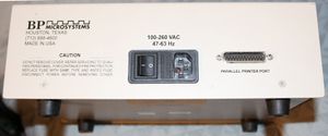
BP-1600
External:
PC interface: parallel port
Chip interface: 3 plug SM
BP-1600 datasheet: [5]
 1400 has a 286 and the 1410 a 486
 1600 supports 1.5V parts
 5000 more devices (probably a lot more by now)
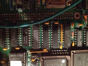
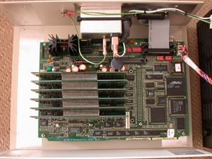
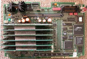
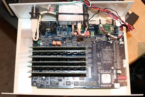
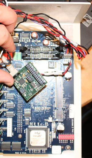
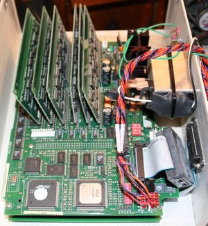
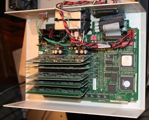
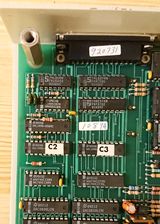
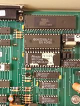
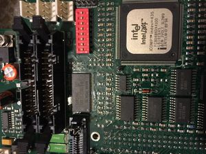
Motherboard:
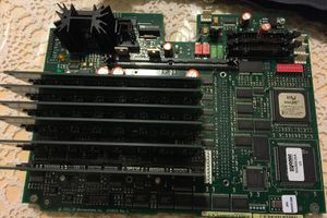
CPCD12A Rev. C
CPU
 intel
 Intel DX4
 iCOMP TM index=435
 PC80486DX4100
 L124EA01
 &EW 3VOLT SL2M9
 INTEL (M)(C) '89 '94
Connectors are numbered with 1 at the side of the top or left of the PCB, oriented such that writing is right side up (ie side with blue trim pot)
J10 (Fan, N/C)
| # | V | Note |
|---|---|---|
| 1 | N/C? | |
| 2 | 16.5 | |
| 3 | 0 | |
| 4 | N/C? |
J11 (Term. 1, N/C)
| # | V | Note |
|---|---|---|
| 1 | 0.0 | |
| 2 | 1.1 | |
| 3 | 0.25 | |
| 4 | 5.1 |
J12 (Term. 2, N/C)
Was this supposed to be identical to above? Broken?
| # | V | Note |
|---|---|---|
| 1 | 0.0 | |
| 2 | 0.0 | |
| 3 | 0.0 | |
| 4 | 0.8 |
Voltage header
| Label | V | Note |
|---|---|---|
| +5V | 5.1 | |
| +3.3V | 3.3 | |
| GND | 0.0 | |
| -3.5V | -3.5 | |
| -5V | -5.0 | |
| GND | 0.0 | |
| +2.5V | 2.5 | |
| PGD | 4.1 | |
| VTH | 1.6 |
Power supply
J4 (12V fans...wtf?)
| # | Color | V | Note |
|---|---|---|---|
| 1 | Red | 35.4 | |
| 2 | Red | 16.5 | |
| 3 | Black | 0.0 | |
| 4 | Black | 5.3 |
J5 (to MB J4 or J20)
| # | Color | V | Note |
|---|---|---|---|
| 1 | Purple | 35.4 | |
| 2 | Orange | 16.5 | |
| 3 | Black | 0.0 | |
| 4 | Red | 5.3 |
J6 (to MB J4 or J20)
| # | Color | V | Note |
|---|---|---|---|
| 1 | Purple | 35.4 | |
| 2 | Orange | 16.5 | |
| 3 | Black | 0.0 | |
| 4 | Red | 5.3 |
BP-2200
"Concurrent Programming System"
PC interface: parallel port
Chip interface: 4X 3 plug SM
BP-2200 datasheet: [6]
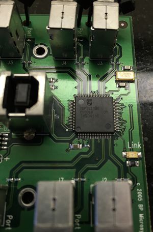
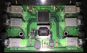
Parallel to USB upgrade
Main page: BPM_WWAVUSBEPP
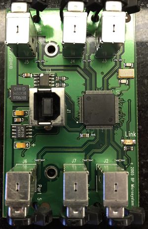
USB hub
Used on gang programmers
EP series
EP-1
PC interface: parallel port
Chip interface: DIP
EP-1132
PC interface: parallel port
Chip interface: DIP-32
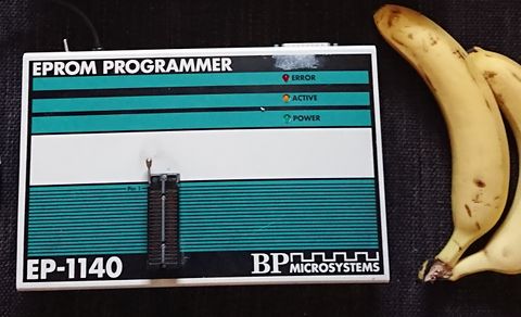
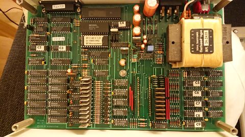
EP-1140
PC interface: parallel port
Chip interface: DIP-40
CPU: Intel 8088
Memory: 8KB/32KB SRAM
Firmware: 8KB/16KB/32KB EPROM
Jumpers:
- EPROM Type
- Left = ON for 27256, OFF for 2764/27128
- Middle = ON for 27128/27256, OFF for 2764
- SRAM Type
- Right = ON for 62256*, OFF for 6264
ON = Up/Towards xtal
OFF = Down/Away from xtal
(* Note: Even if the firmware can deal with more RAM, BPDos/BPWin might expect it to be hardcoded and crash the programmer if not set right.)
Powersupply:
- Unregulated
- -13.4V/+11.1V
- -44.8V/+38.8V
- Linear
- +5V (TTL, CPU, DAC)
- +6V (CMOS)
- -3V/+29V (Op-Amps)
- Variable
- Overcurrent-protection
- 13 DACs (DAC0830LCN)
- 4 quad op-amps (TL084CN)
- Routing
- 12 transistors for VCC/VPP (NSDU01)
- 11 transistors which has something to do with VPP-pins (PN2222)
- 8 transistors for GND (IRF-Z15)
Pinout:
- 20 normal IO pins
- 1 pin with VCC feature
- 11 pins with VPP feature
- 8 pins with GND feature
- Out of all the pins, 4 have some unknown additional feature
Pin features:
______	   _____   _____     ______
_	VPP	|_|	VCC       _
_	Pin*		Pin       _
_	Pin*		VPP       _
_	GND		VPP       _
___	Pin		VPP     ___
_	Pin		VPP       _
_	VPP		VPP       _
_	Pin		Pin       _
_	Pin		VPP       _
______	Pin		VPP  ______
_	GND		GND       _
_	GND		Pin       _
_	Pin		Pin       _
_	GND		Pin       _
___	Pin		VPP     ___
_	GND		VPP       _
_	Pin		Pin       _
_	GND*		Pin       _
_	Pin*		Pin       _
______	GND_____________Pin  ______

* Unknown additional feature
PLD series
PLD-1128
PC interface: parallel port
Chip interface: DIP-28
CPU: Zilog Z80
Memory: 2KB/8KB SRAM
Firmware: 8KB/16KB/32KB EPROM
Jumpers:
- EPROM Type
- W1 = ON for 2764/27128, OFF for 27256
- W2 = ON for 2764 , OFF for 27128/27256
- SRAM Type
- W3 = ON for 6116, OFF for 6264*
- Unknown
- Jumper up by the parallel port = ??
ON = Up/Towards CPU
OFF = Down/Away from CPU
(* Note: V1.05d firmware only supports 6116-type SRAM)
Powersupply:
- Unregulated
- -10.9V/+10.3V
- +52.5V
- Regulated
- +5V (Digital)
- -5.8V/+11.3V (DAC)
- -5.8V/+30V (Op-Amp)
- Possibly more
CP series
CP-1128
PC interface: parallel port
Chip interface: DIP-28
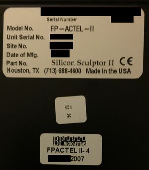
Silicon Sculptor
Actel programmers made by BPM.
As these cost less than the "real" BPM programmers, presumably can't be used with normal BPM software and/or work with other adapters
Silicon Sculptor 1
Has 2 headers (left/right) that adaptors plug into
Interface: parallel port
There is version with 1 connector and a version with 6 connectors
1X markings
 Silicon Sculptor
 FAIL
 ACTIVE
 PASS
 START
 ACTEL DEVICE PROGRAMMER
 BP MICROSYSTEMS
Silicon Sculptor 2
http://www.actel.com/kb/article.aspx?id=SL1039
- WWAV20 motherboard with pin driver boards (PD8As)
- 286 processor
- 2MB onboard RAM
- an additional 4MB SIMM to support concurrency
Markings:
 Silicon Sculptor II
 Actel
 FAIL
 ACTIVE
 PASS
 ACTEL DEVICE PROGRAMMER
 BP MICROSYSTEMS
mcmaster notes
2018-09-12
- Open SS2
- Think this was the eBay unit?
- PCB is identical to one used in BP-1600
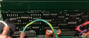
- Both have blue bodge wire
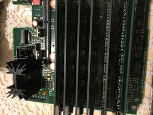
- SS2 has RAM installed
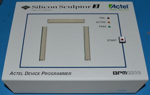
Actel Silicon Sculptor 3
Above: DO NOT TOUCH!
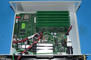
This appears to be a crippled BP-1410 (however, it has the front-panel button and the 512MB of RAM present in the BP-1710). No analysis has been done to figure out where the devices differ (firmware, FPGA, host, etc)
Product page: [7]
I love how they switched from roman numerals to Arabic numbers. Maybe they'll call the next one Silicon Sculptor D…
Has 3 headers (left/right/top) that adaptors plug into
Interface: USB
Markings:
 Silicon Sculptor 3
 Actel
 FAIL
 ACTIVE
 PASS
 START (button)
 ACTEL DEVICE PROGRAMMER
 BP MICROSYSTEMS
External
Motherboard
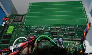
Main assembly:
Driver board:
